Electrical Circuit Diagram For Bjt And Fet Common Collector
Electronics bjt and fet Difference between bjt and fet : working & their characteristics Solved: 9) a
BJT and FET - 1 - Electrical Engineering SSC JE (Technical
Fet principles and circuits — part 1 Mosfets transistor transistors bipolar mosfet cons circuits comparing приготовления домашнего Comparing mosfets with bjtransistors
Circuits fet circuit gate jfet common channel part principles basic figure nuts
Mosfet switch circuit configuration channel operation mosfets used enhancement when byjus switches basics typesThe summary results for both bjt and fet circuits Electronic – is a ua current fet or bjt circuit design possibleDifferent transistors in electronics at josh flores blog.
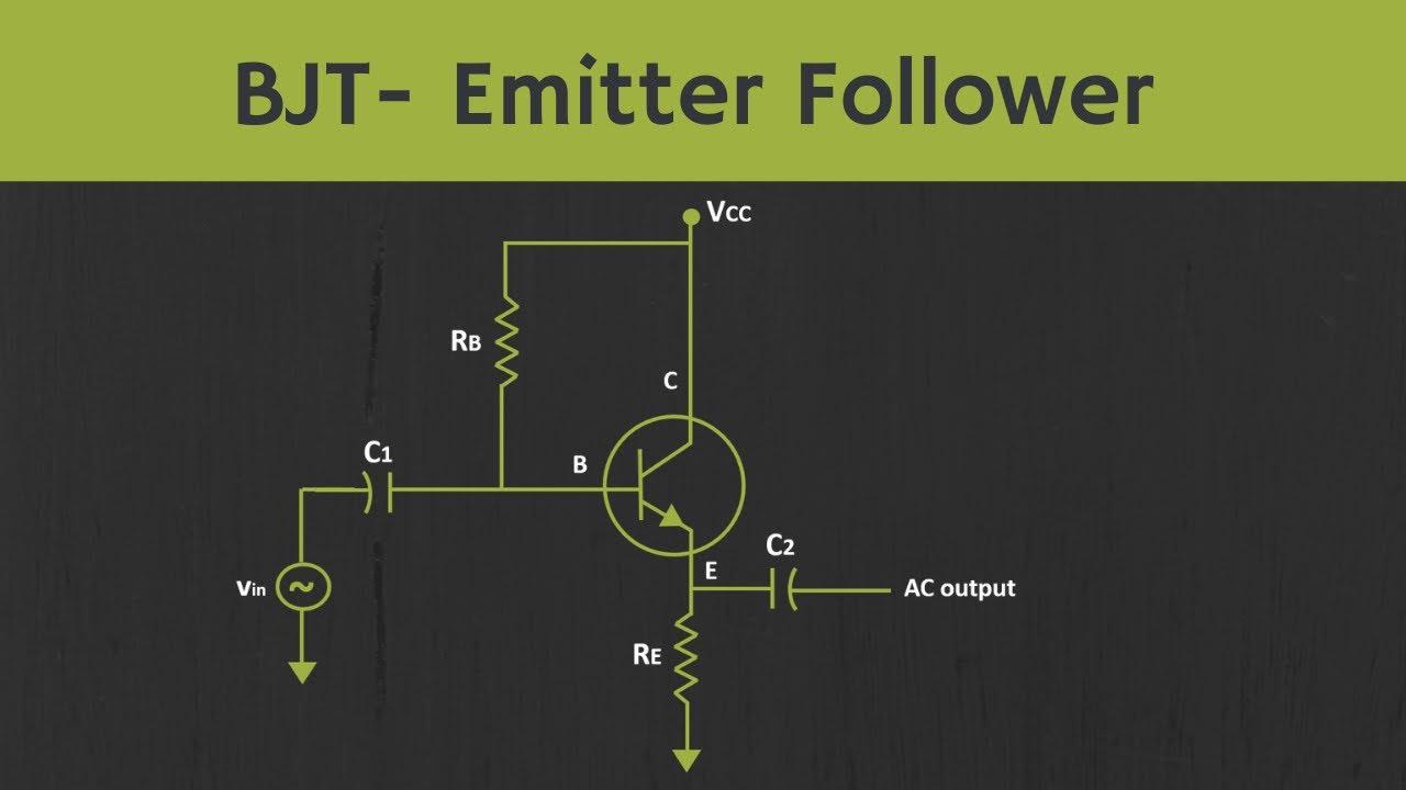
Common collector circuit diagramFet jfet circuits current constant biasing principles part basic figure system Fet preamplifier impedance circuits eleccircuit schematics bias voltage radio controlCircuit transistor bjt current amplification containing given questions stack.

Bjt and fet amplifiers
Entwicklung von partikel merchandising why is mosfet better than bjtBipolar junction transistor (bjt) basics #fetprinciples and circuits — comparison of transistor and #jfetsymbolsBipolar junction transistor.
4 preamplifier circuits using transistorsSimple fet circuits and projects – homemade circuit projects Jfet schematic channel symbols field effect junction symbol transistor electronics circuit basics electrical drain choose board source constructionUnderstanding the difference between bjt and mosfet and how to select.
Solved 1. what is the difference between fet and bjt? 2.draw
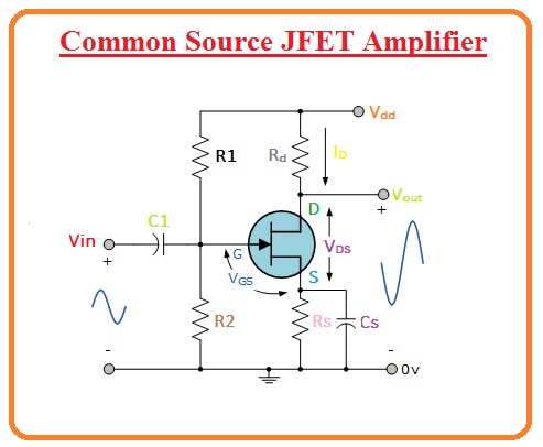
Common source jfet amplifierElectrical – high-power switching using mosfets – valuable tech notes Bjt circuit transistor bipolar junction basic ce analysis figureDifference between bjt and fet.
Jfet biasing methodThe basic circuit of the source-coupled jfet oscillator. Unit 3 bjt and fet, important question answer in electronic engineeringDifference between bipolar junction and field emmiter transistor.

Bjt amplifier bipolar junction transistor analog transistors bjts
Jfet biasing method bias voltage divider biasedCircuit diagram of bjt Bjt fet difference transistor vs between bipolar explained junction working field detail explain going here basics its emmiterJfet oscillator coupled.
Jfet circuit diagramBipolar junction transistors (bjts) Fet principles and circuits — part 2Jfet n-channel and p-channel schematic symbols.

Ne gece yeri uzun ömürlü bjt switch circuit kuğu yıpratmak çim
Fet bjtFet oscillator circuits Bjt and fetJfet amplifier circuit bjt comparison.
Transistor bipolar junction bjt transistors emitter npn .

Electrical – High-Power Switching using MOSFETs – Valuable Tech Notes

Understanding the Difference Between BJT and MOSFET and How to Select

FET Principles And Circuits — Part 2 | Nuts & Volts Magazine

The summary results for both BJT and FET circuits | Download Scientific

FET Principles And Circuits — Part 1 | Nuts & Volts Magazine

JFET Biasing Method - The Engineering Knowledge

Entwicklung von Partikel Merchandising why is mosfet better than bjt